Wedge gate valve
Wedge flat gate valve / Wedge oval gate valve / Wedge round gate valve
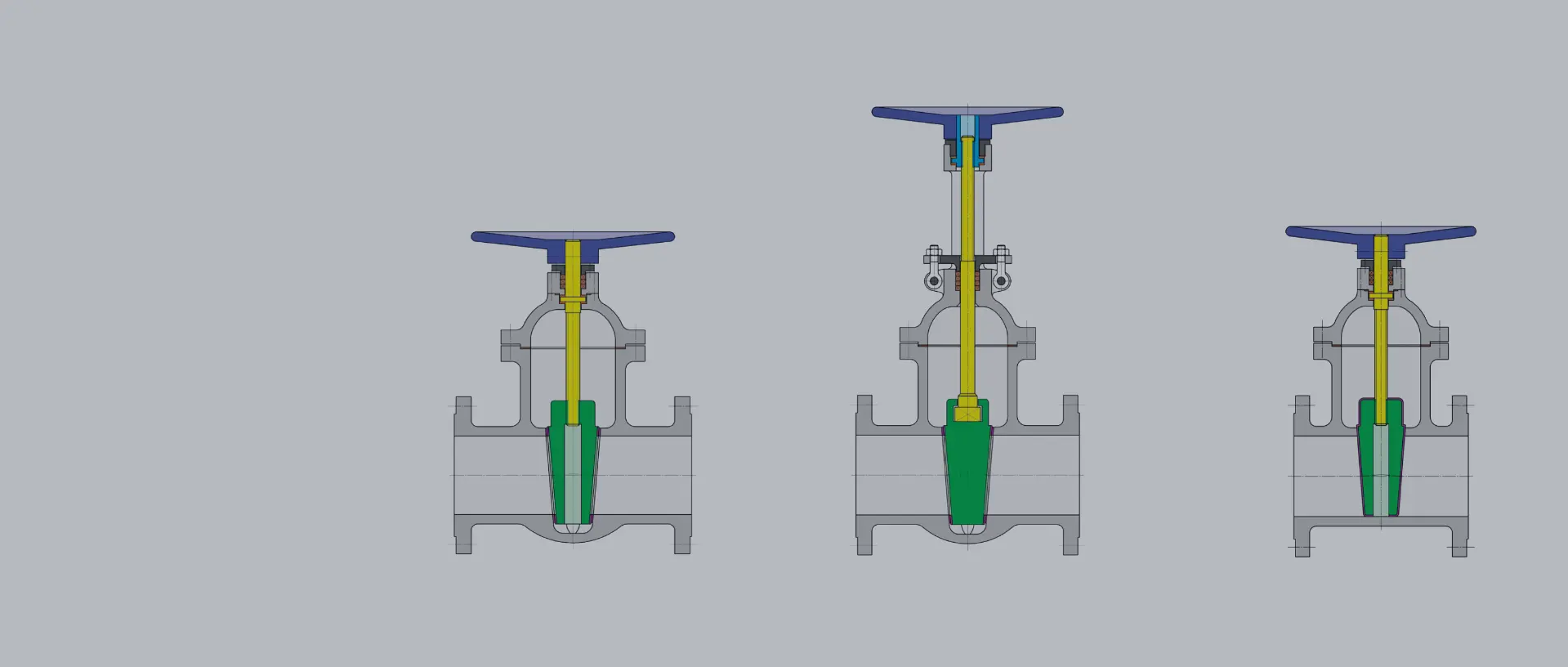
The names Wedge flat, Wedge oval, and Wedge round gate valves date back to the early days of valve construction. They refer, on one hand, to the total lengths: Wedge flat gate valves have a significantly shorter (= flat) total length than Wedge oval or Wedge round gate valves. In the past, they could only be manufactured for the low-pressure range in PN 6 up to a maximum of PN 10. Today, this is possible for the water and wastewater sector up to PN 25.

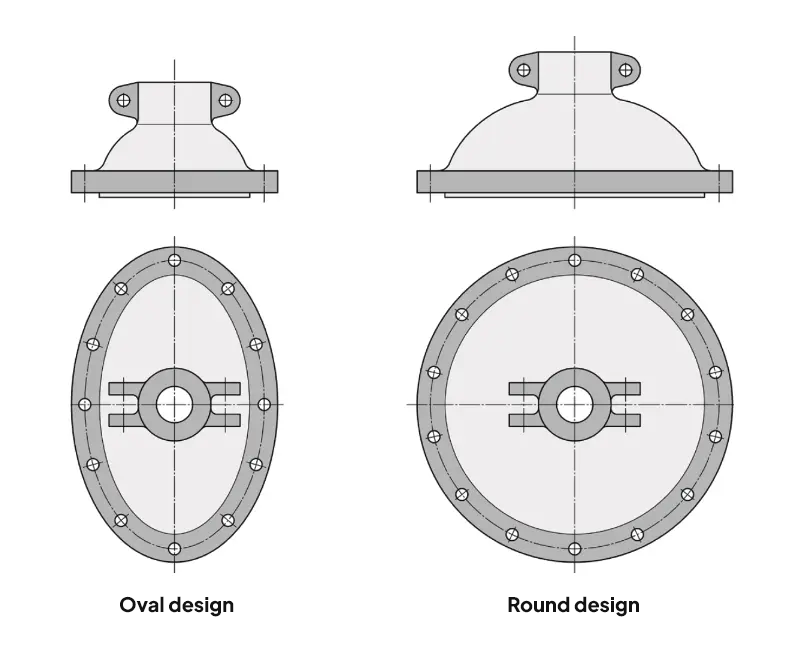
On the other hand, wedge oval and wedge round slider are designated according to their housing design. In the top view, wedge oval sliders have an oval-shaped upper part, while wedge round sliders have a round one. The initially available wedge oval sliders were manufactured for the medium pressure range PN 10 and PN 16/25. At higher pressure levels, starting from PN 25, the slider upper part had to be designed more robustly, which is why the traditional oval shape was abandoned in favor of a round upper part.
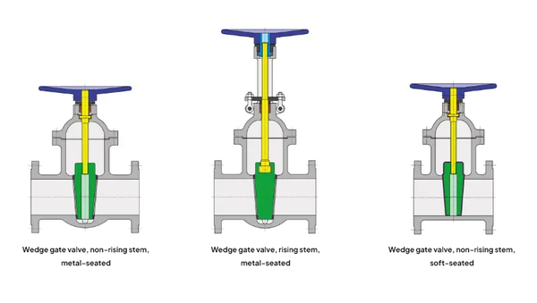
The sealing of these fittings is achieved using a wedge-shaped shut-off element – hence the name wedge gate valve (see also types of shut-off wedges).
Wedge gate valves can be flow-through in both directions due to their design and are sealing on both sides. However, they are not suitable for regulating and are only used as shut-off valves in open or closed positions (On/Off). In intermediate positions, the sealing wedge begins to flutter, resulting in turbulence and increased material wear on the wedge, housing, and sealing surfaces.

Internal / External Spindle
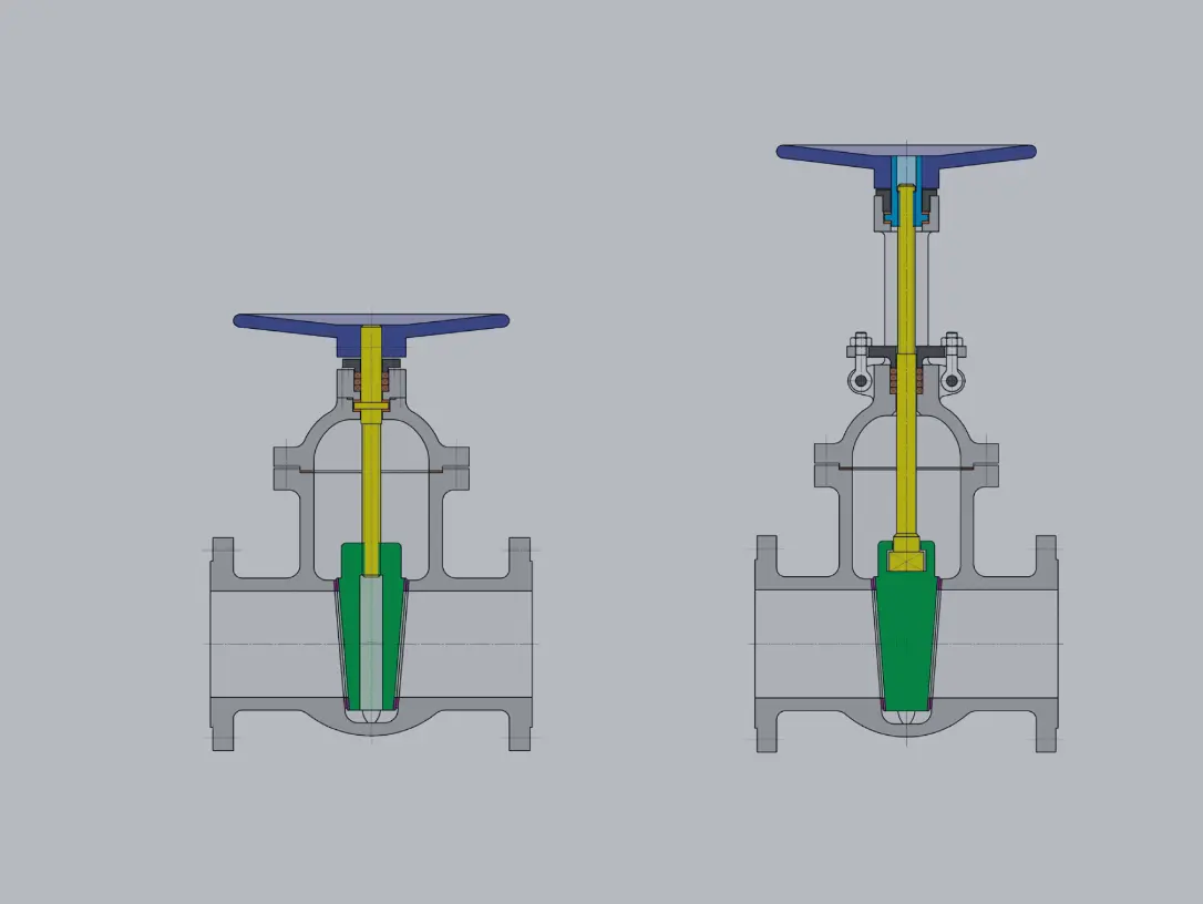
Nowadays, valves with internal spindle are most commonly used, where the threaded part of the spindle is located in the valve body. This compact design allows for a low upper part and is more cost-effective to manufacture than valves with external spindle.
When the spindle is actuated, it rotates into the thread of the valve wedge. This pulls the valve wedge upwards into the valve upper part and opens the valve. By turning in the opposite direction, the valve is closed again.
The spindle sealing can optionally be achieved via an adjustable packing or by multiple O-rings, which are virtually maintenance-free.
Valves with internal spindle are only suitable for non-aggressive liquids and gases. Because the spindle thread is in the media flow, the use of aggressive media can lead to contamination and subsequent "seizing" of the thread.

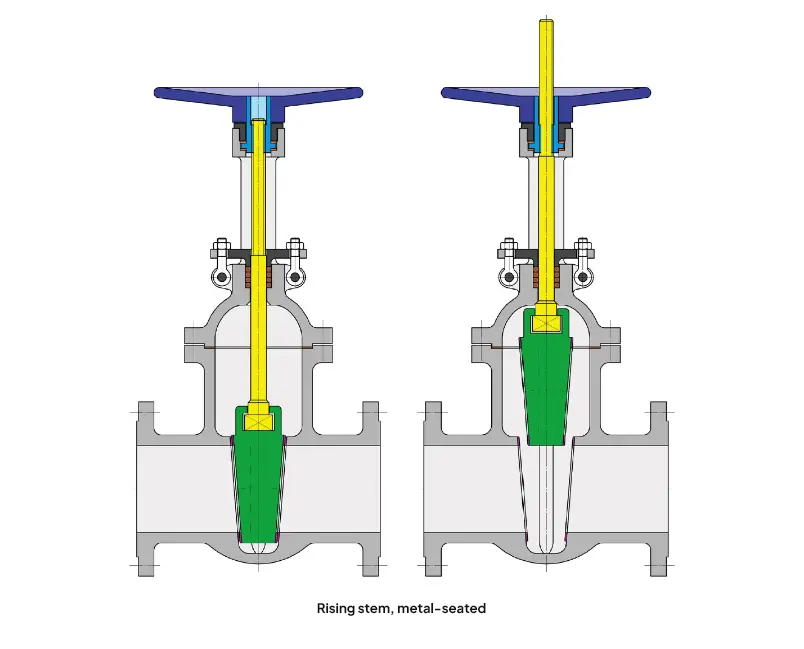
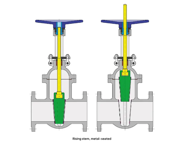
External spindle – Construction and Advantages
In valves with external spindles, the threaded part of the spindle rod is not located inside the housing, but rather at the top, outside of the valve upper part. The smooth area of the spindle sits within the housing and is form-fit connected to the valve wedge. The spindle nut is mounted in the so-called block head above the valve housing. When operating the valve, the spindle nut is rotated and "pulls" the spindle, including the wedge, upwards, thus opening the valve.
The advantage compared to valves with internal spindles is that they are also suitable for aggressive media. Both the spindle thread and the spindle sealing (packing) are located outside the media flow, which means that "seizing" of the spindle thread is nearly impossible.
Based on the position of the spindle, it can also be quickly recognized whether the valve is open or closed.
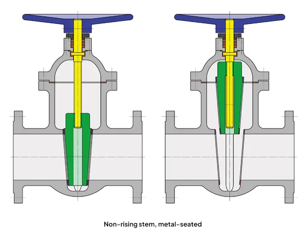
Rising / Non-rising spindle
- Rising spindle = always external
- Non-rising spindle = always internal
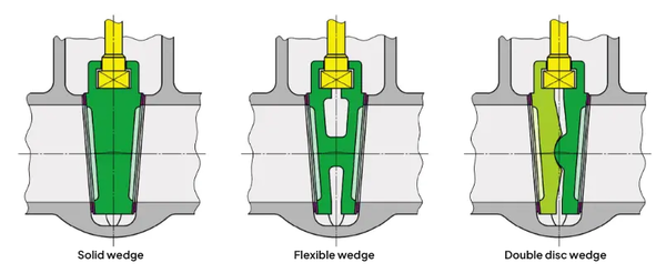
Types of Shut-off Wedges
Rigid Wedge and Flexi-Wedge
The shut-off element of a gate valve is wedge-shaped and typically consists of two plates connected to each other.
If the two wedge plates are firmly connected (welded), they are completely immovable, and this is referred to as a rigid wedge. The two wedge sides and the "counterparts" in the housing, the housing seats, must be machined very precisely and flat to ensure a secure sealing of the valve against the medium.
In small valves under DN 40, as well as in very large valves, the rigid wedge is usually made of one piece (forged material, cast). It is particularly heavy and therefore costly, especially in large nominal sizes.
In the case of the Flexi-Wedge, the two wedge plates are not rigidly connected but only joined by a bridge in the middle. This makes the two plate halves elastic (flexible) to a certain extent and allows them to adapt more accurately to the housing seats. The achievable tightness here is significantly higher than that of a valve with a rigid wedge.
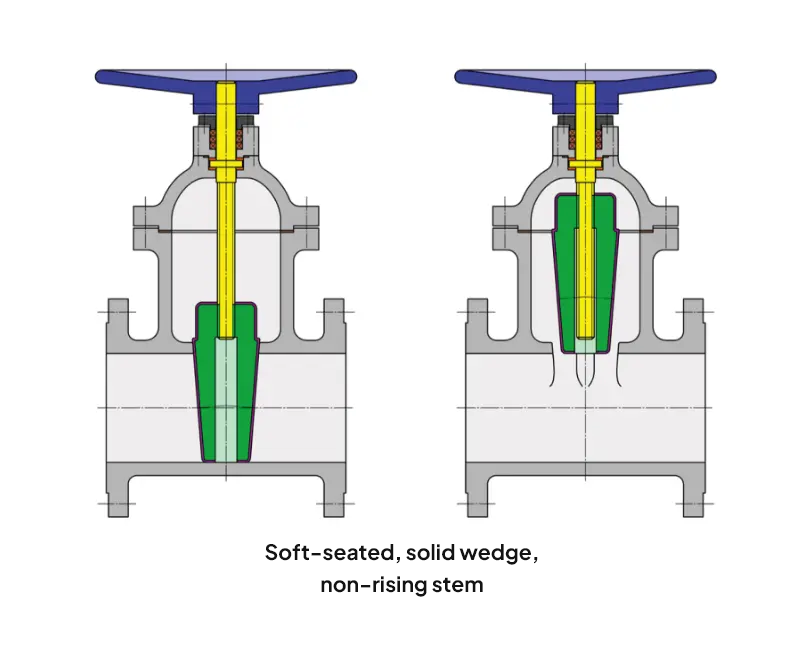
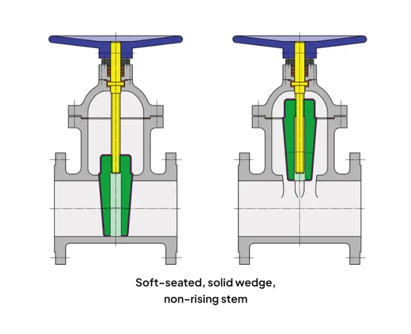
Due to its good sealing and low weight, valves are now mostly made with a Flexi-Wedge. Exceptions are the soft-sealing valves, which are mainly used in water and wastewater applications. In these valves, the rigid wedge is completely vulcanized with NBR or EPDM, achieving high tightness.
Double Plate Wedge
The two sealing plates are movably connected to each other, e.g., through ball segments or ball shells or via a spring mechanism. Since they are self-adjusting, a high tightness is achieved, and the valves can be opened and closed with less effort. Due to the complex and costly manufacturing process, double plate valves are almost exclusively used for high-pressure applications in power plants as main shut-off valves at the main steam outlet or at steam generators.

Metallic sealing gate valves
The classic gate valves are very versatile: suitable for liquid and gaseous media as well as for media laden with dust or hard particles, for aggressive or abrasive media, in high-temperature and high-pressure applications. Of course, the materials used and the design (internal or external spindle) must be matched to the respective operating medium.
In all metallic sealing valves, the sealing seats/sealing rings in the housing and on the wedge are made of metallic materials. To achieve higher sealing, wear resistance, and/or corrosion resistance, sealing rings made from a variety of materials can be used.
A major disadvantage of metallic sealing gates is that impurities present in the medium (e.g., sand, lime) settle in the lower part of the housing (the gate bag). These deposits can prevent the complete closure of the wedge, which then leads to a leakage.
Cobalt-chromium seat
“Stellite” is a hard alloy based on cobalt-chromium and serves as protection against high wear loads from the working medium. In the case of the gate valve, the housing seats and possibly the wedge as well as the spindle are overlaid with Stellite when exposed to aggressive media or superheated steam.
Unprotected, standard materials such as 1.4021 or 1.4571 would not withstand the high stresses for long. This coating can be applied by welding or flame spraying.
Soft-sealing gate valves
Soft-sealing gate valves are mainly used in the field of water and wastewater. Since the spindle is sealed maintenance-free by O-rings, soft-sealing gate valves are also suitable for use with gas (natural gas, biogas).
In contrast to the classical metallic sealing gate valves, they have a smooth, full passage without a gate pocket. This offers the advantage that the valves can be pigged and the pipeline can be fully cleaned if necessary. A so-called pig is a cleaning or inspection device that is pressed through the pipeline using pressure.
Another advantage is the high tightness of the valves in the passage. The gate wedge is vulcanized with NBR or EPDM, achieving a tightness according to DIN EN 12266-1, leakage rate A! Moreover, these valves are conditionally suitable for vacuum.
Due to the rubber coating, soft-sealing gate valves are not suitable for high temperatures, high working pressures, or abrasive media. Like all other valves, they are suitable "only" for shutting off and not for regulating the operating medium.
Screwed / welded cover
This refers to the way the gate valve body is connected to the upper part.
In the case of a screwed cover, as the name suggests, the body and upper part are screwed together. The connection is removable, so that, for example, the internal parts of the gate can be processed or replaced at any time for maintenance or repair purposes.
If a gate valve is difficult to access or should be installed underground, the version with a welded cover is usually used. An unwanted loosening of the cover screws, for example due to vibrations in operation, thermal expansion, wear of the cover gasket, etc., is thereby excluded, and the tightness to the outside is ensured. However, in the case of repair or maintenance, the valve must be completely removed from the pipeline, and the cover connection must be separated in a workshop.
Drive types
The classic drive type for gate valves is the handwheel. The international standard is that the gate valve is closed by turning the handwheel clockwise and opened by turning it counterclockwise.
In addition, there are the following actuation types:
Gear with handwheel:
If the required actuation forces are too high, a reduction gear with handwheel can be used.
Quick-closing lever:
Instead of the handwheel, a bearing block with a lever is attached to the upper part of the gate valve; by pulling upwards, the gate valve opens abruptly, and by pushing down the lever, it closes.
Sprocket:
If the gate valve is installed at a greater height, a sprocket can be used for actuation. A chain is placed over the sprocket and secured against falling with a guide bracket. Pulling on the chain allows the gate valve to be opened or closed from the ground.
Operation key:
Instead of the handwheel, a square section is attached to the end of the gate valve spindle. The gate valve can then be actuated with a wrench or (when installed underground) from above with a T-key.
Automatically actuated gate valves
Electric Drives:
Electric actuators can be precisely tailored to the requirements of the gate valve and can be operated optionally with three-phase current, alternating current, or direct current.
While they are costly to purchase, they offer a long service life and only low maintenance costs (simple installation, no energy consumption during switching pauses, maintenance-friendly).
The switching times can be variably selected according to the application, between approximately 20 seconds and several minutes.
Pneumatic drives:
They are operated with compressed air, are less expensive than electric drives, have short switching times, and are maintenance-friendly. However, a compressed air supply line and a solenoid valve for control are required.
A distinction is made between double-acting and single-acting pneumatic drives.
Double-acting means that the drive requires compressed air to open the gate valve and also to close it.
Single-acting means that compressed air is required either to open or to close. The reset occurs automatically via a spring.
Hydraulic drives:
The same principle as with pneumatic drives. However, these drives are operated with oil or water-based liquids (hardly flammable).
Remote-operated gate valves
Gate valves cannot always be operated directly at the installation site, e.g., when installed in a shaft, underwater, or in the ground. The operation is then performed manually via a drive rod or a spindle extension, or by an electrical, pneumatic, or hydraulic drive. Depending on the structural conditions, it may be necessary to additionally install deflections with two or more universal or ball joints, as well as a floor column with a handwheel or drive.
Installation assembly
Water and wastewater pipelines, including their gate valves, are often installed underground. To operate the valves, an installation assembly is used. The installation assembly consists of an extension rod that is firmly connected to the valve spindle. To protect against contamination from seepage water and the surrounding soil, the rod is covered by a PE pipe. The upper end of the extension is equipped with a square shape, on which the so-called T-handle is placed to operate the valve. A street pillar forms the ground-level completion and serves as the visible indication of the installation assembly located below.
A project in mind?
We can help you!
Please feel free to contact us and we will discuss together how we can assist you!